|
|
|
SWITCH CIRCUIT DIAGRAM
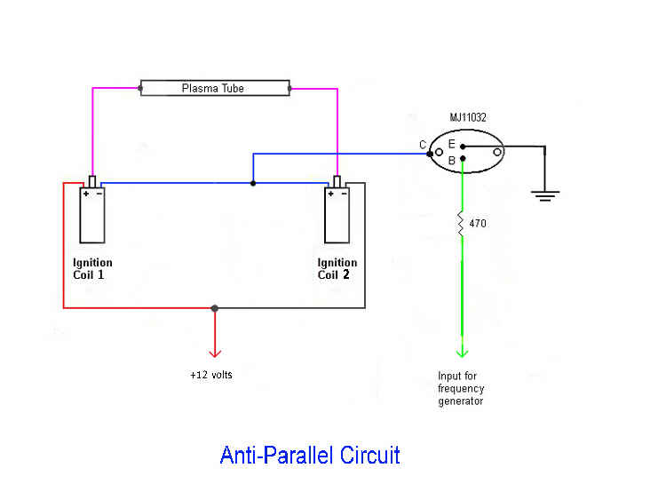
The following is a Switch Circuit Diagram, which shows the wiring and connections of 1 - 4PDT Switch, 2 - Ignition Coils, 1- Power Transistor and 1 - Plasma Tube. The 4PDT Switch is shown in my UNIQUE Series-Aiding Circuit Position. The Position of an Anti-Parallel Circuit can be achieved, when the Switch is flipped in the opposite direction. The 4PDT Switch is mounted on the Front Panel of the High Voltage Power Supply of my ELECTRO-CELLULAR ENERGIZER II™ Plasma Tube Unit. 
NOTE: Test Instrument Wire was used to connect 1 - 4PDT (or 3PDT) Switch, 1 - NPN Power Transistor (T0-3), 2- Banana Jacks and 2 - 6 Volt/1.5 Ohm Automotive Ignition Coils, plus Aquarium Silicone Rubber was also placed on the Primary Terminals of the 2 - Ignition Coils and 2 - Banana Jacks (metal parts - E.C.E. I only), thus PREVENTING High Voltage ARCING and Corona Discharge, which can result in the eventual BURN-OUT of the NPN Power Transistor and/or 2 - 6 Volt/1.5 Ohm Automotive Ignition Coils. |